Kinetic Sculpture Assemly:
This project was an exploration of microcontroller programming, electronics, mechanisms, and functioned as a prototyping experience for my final project. My choice of design was a mechanical hand that would open and close at set intervals, with an unintended side-effect of expression my frustations during the construction of the sculpture.
The first step in this project was sketching out my ideas and then implementing them into a CAD model through Fusion360. I started with some hand sketches of my ideas, which served as a base for my first attempts.
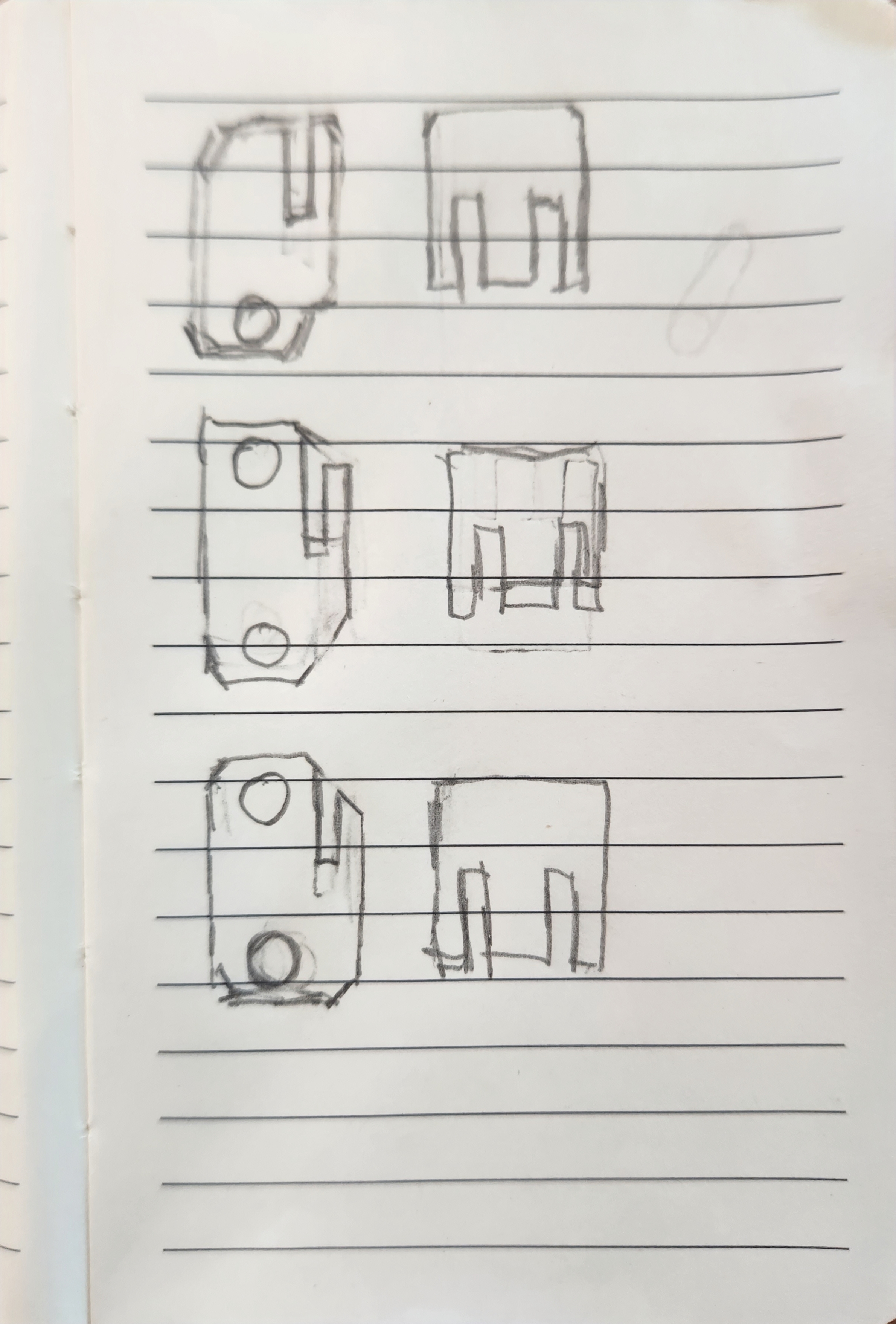
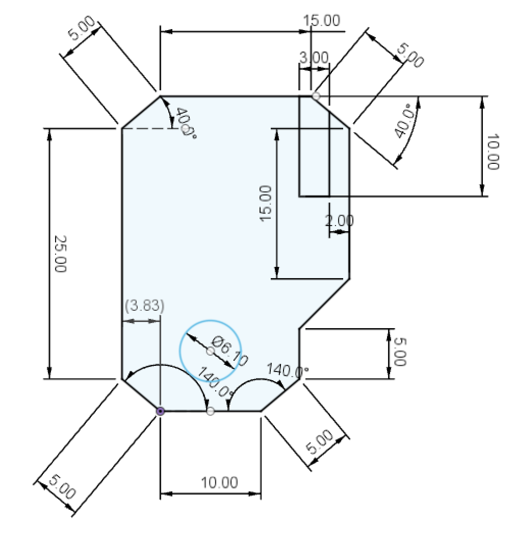
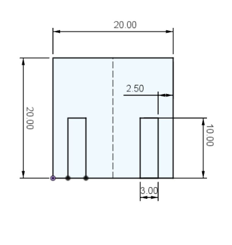
Fig. 4.1: First attempts at designing components
After some trial and error, I settled on this design for the finger assembly. This design would allow for free movement of the fingers while having channels for the attachment and movement of aritificial "tendons" using nylon string. Another plus is the ease of assembly through press-fit techniques, requires little to no adhesive.
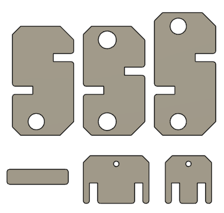
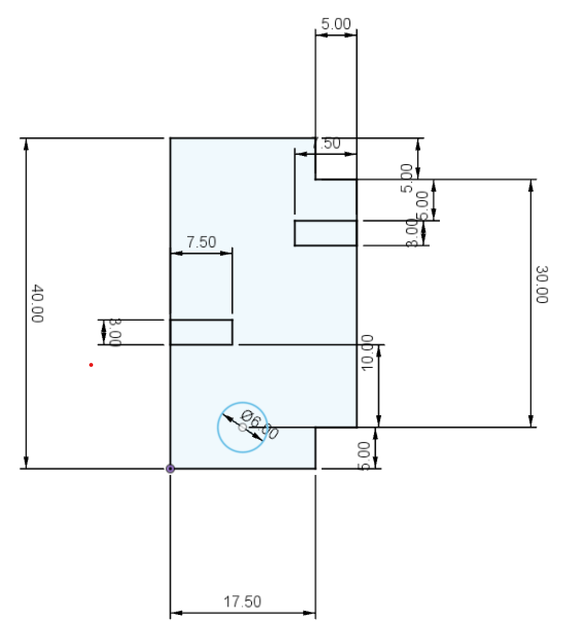
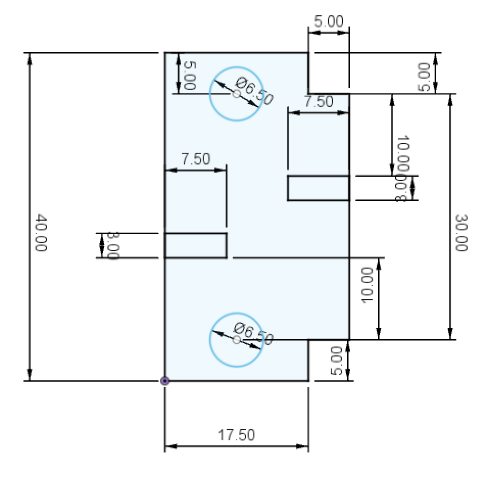
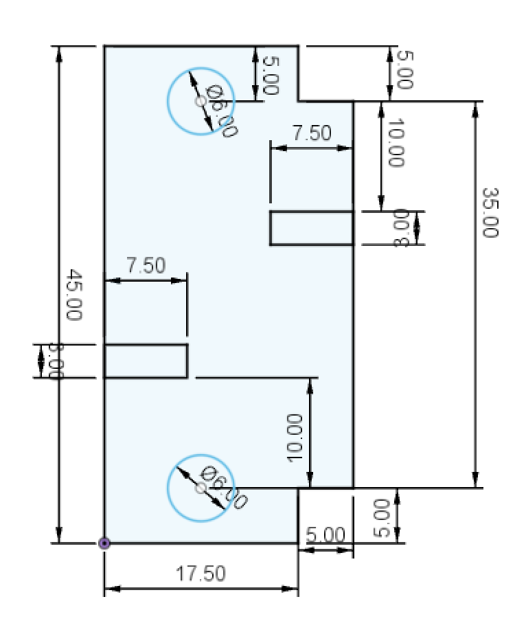
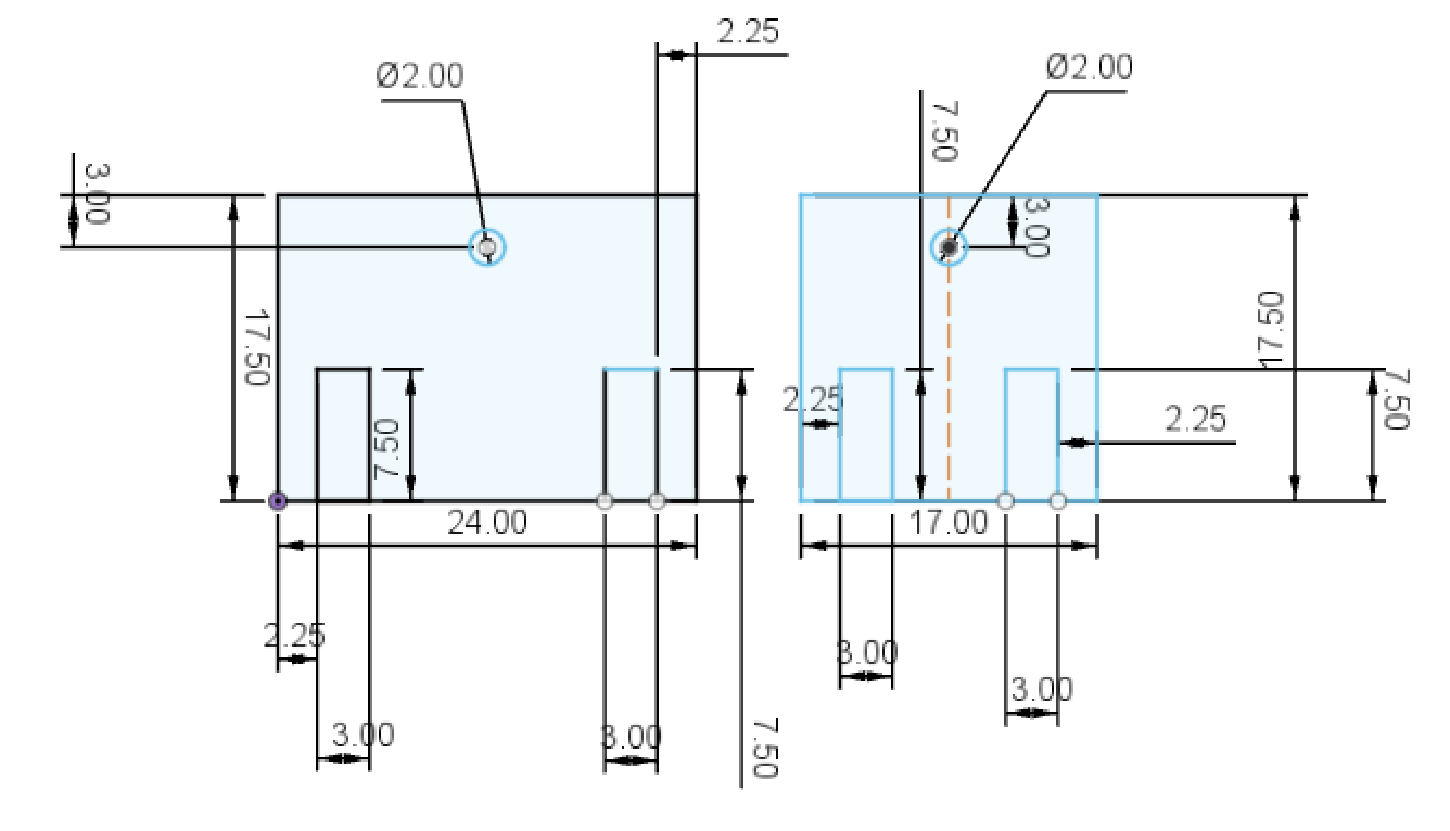
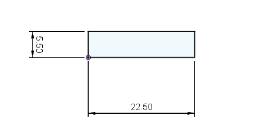
Fig. 4.2: Chosen design for components. Thickness = 3.2mm, Kerf = 0.2mm.
Now with the design settled, I exported my model to Rhino and used a laser cutter with wood as my stock material to manufacture the parts needed for the fingers. For assembly, i used some hot glue as an extra measure to solidify the construction on the hinges.
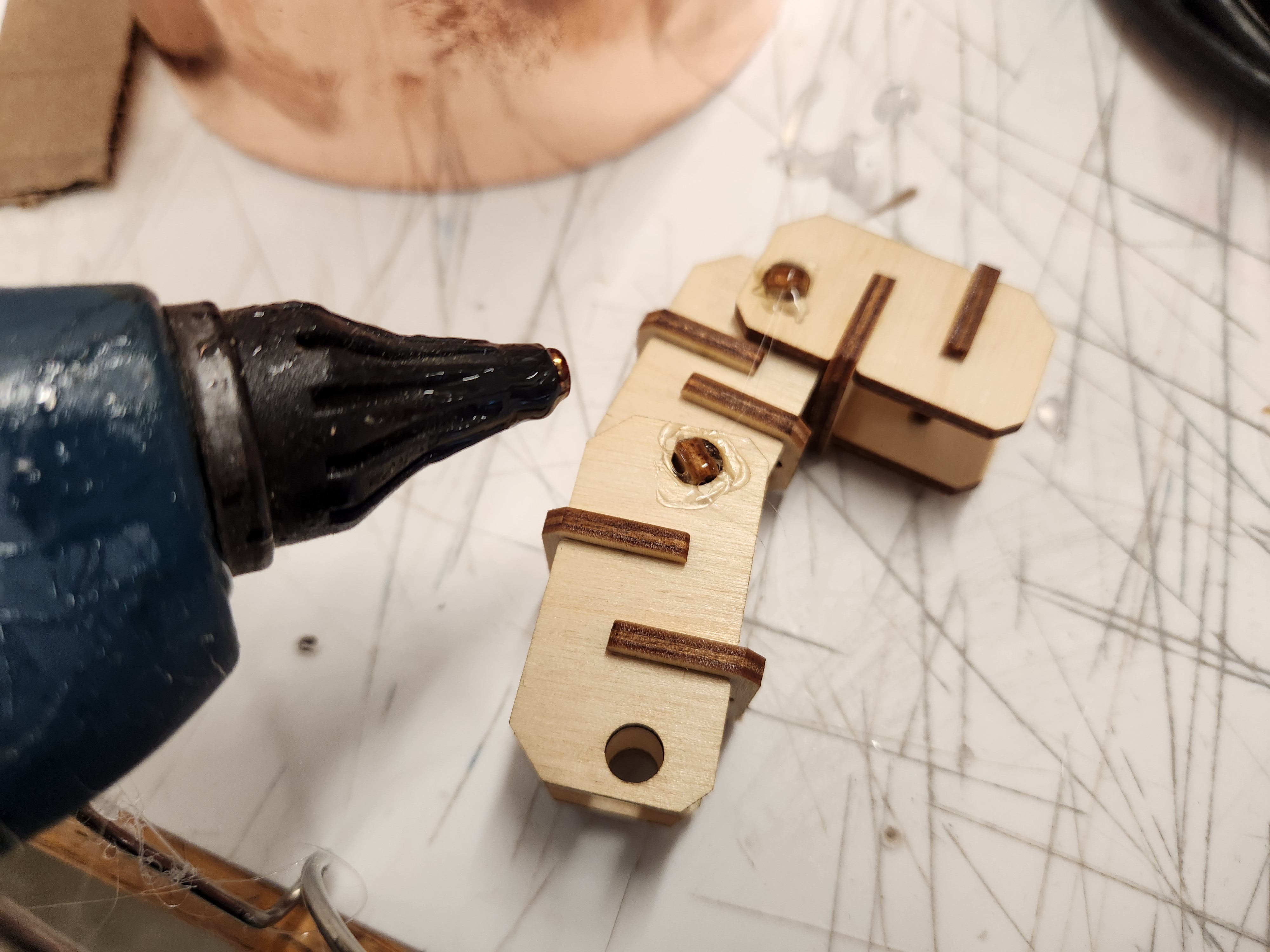
Fig. 4.3: Finger assemly using hot glue to hold hinges
Once I had the four fingers constructed, the next step was to design a palm assembly to attach the fingers while having channels for the nylon thread to flow and come together. I used more press-fit pieces that would also have a section of material sticking out at the ottom to be attached at a base. Here are the Fusion360 models:
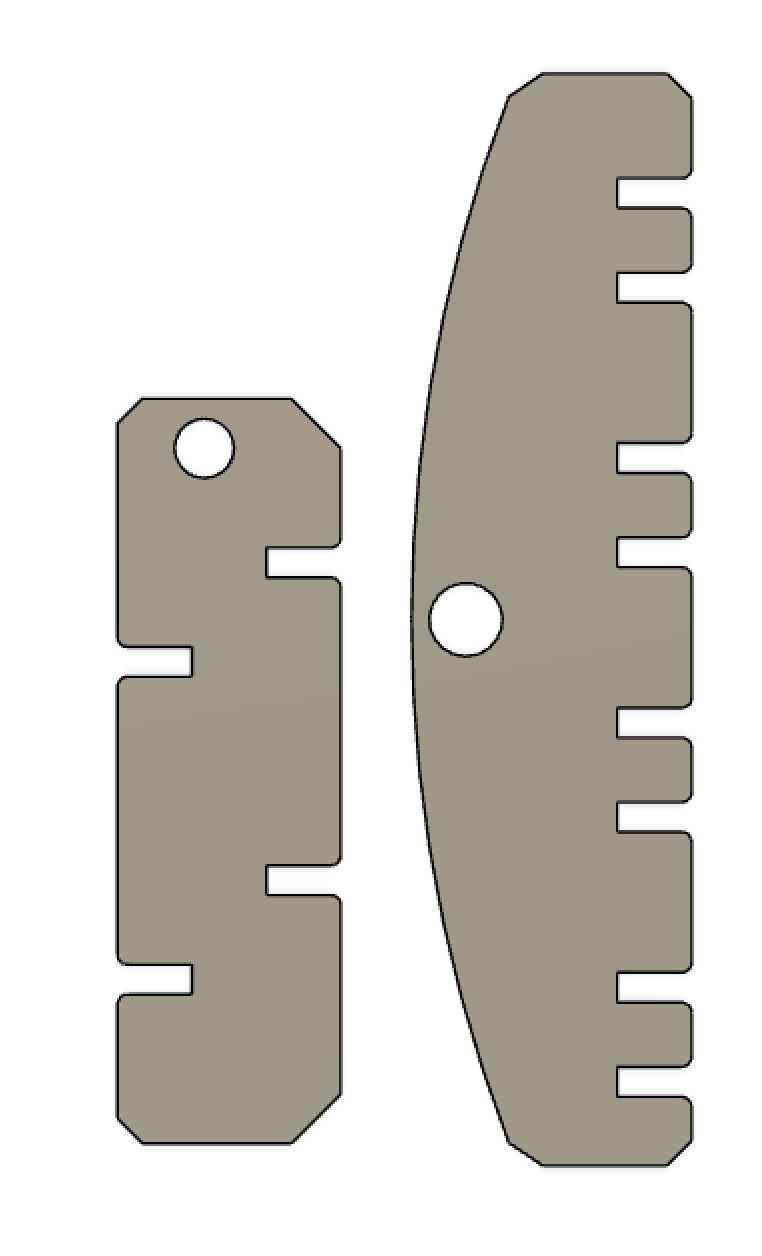
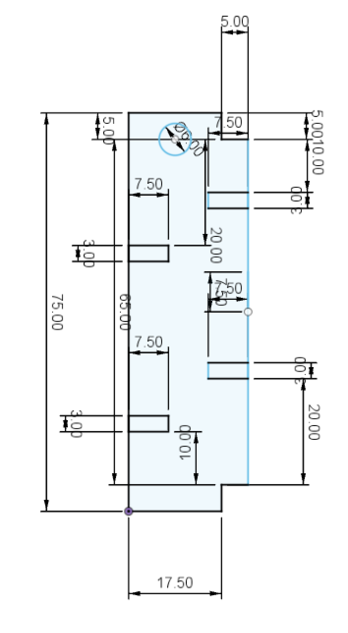
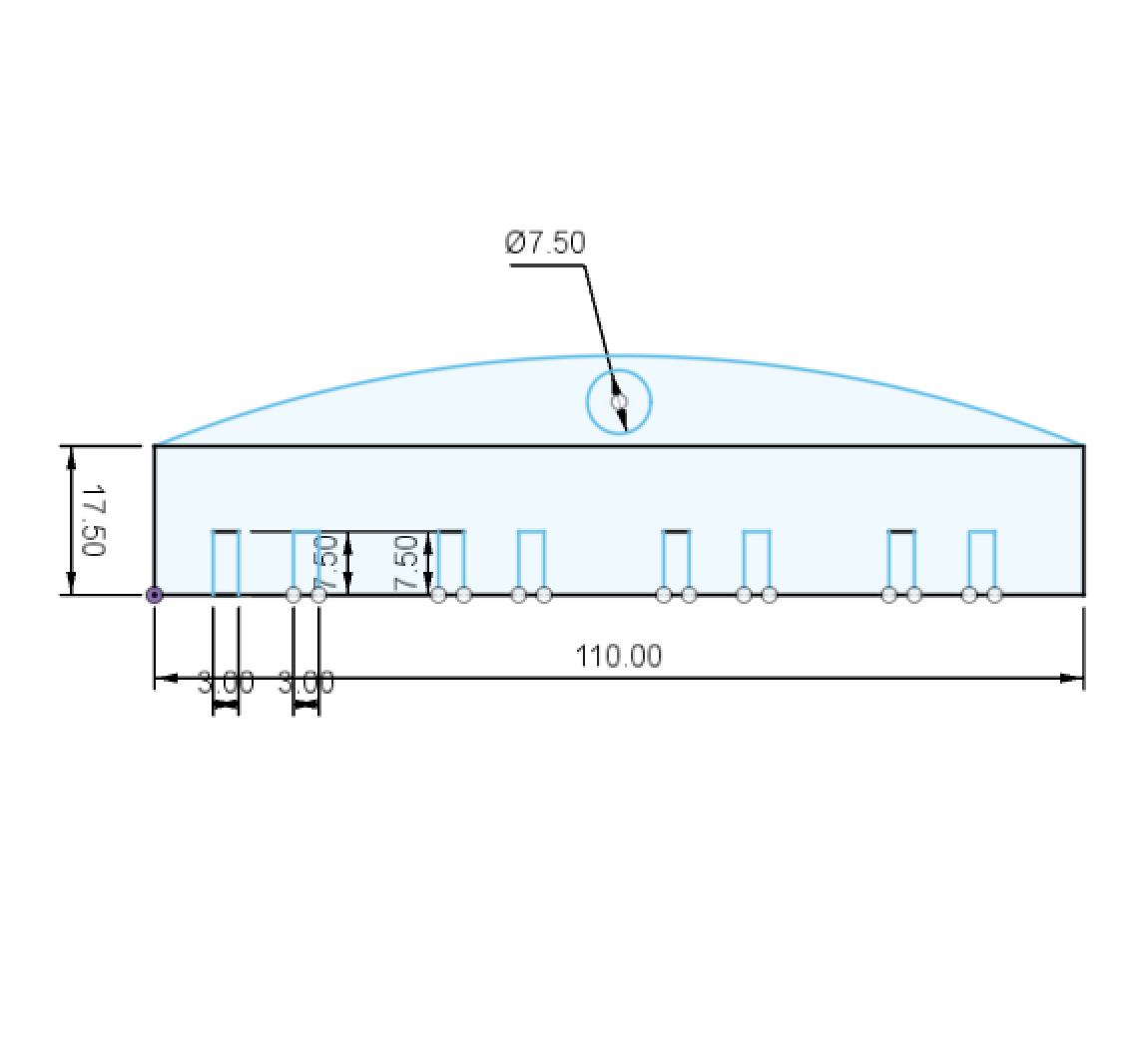
Fig. 4.4: Palm assembly parts and dimensions
I then laser cut the palm assembly, just as I did with the previous parts. I was then able to attach the fingers together to form the entire hand. The next step was to make a base for the hand to rest on, along with a housing for the motor and spindle. Here's a video of the hand assembly:
Fig. 4.5: Completed hand assembly
Now I needed to design a base that could hold the spindle for winding up the nylon thread, along with a way to attach the gearbox motor to the assembly. I used a simple box design with notches at the top for attaching the hand assembly, supports that include a hole for the spindle and attachment points for the motor, and a stable base. Here is the CAD model:
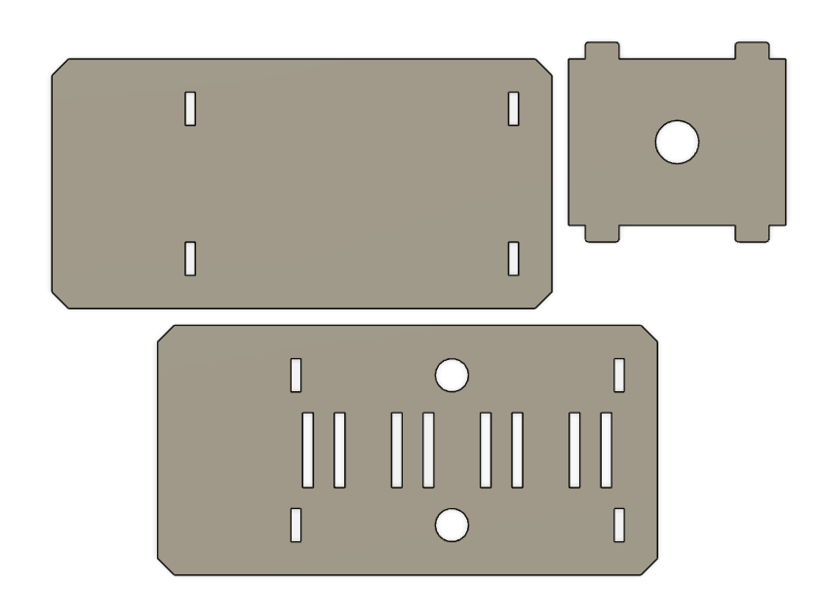
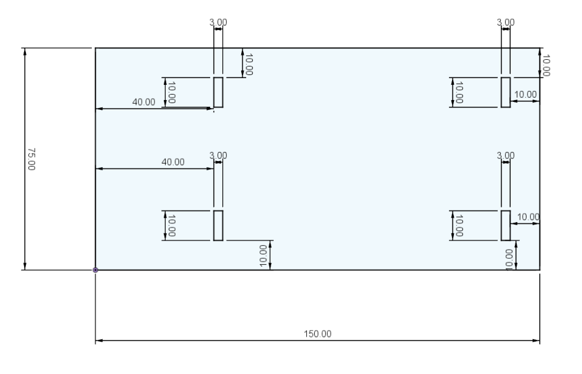
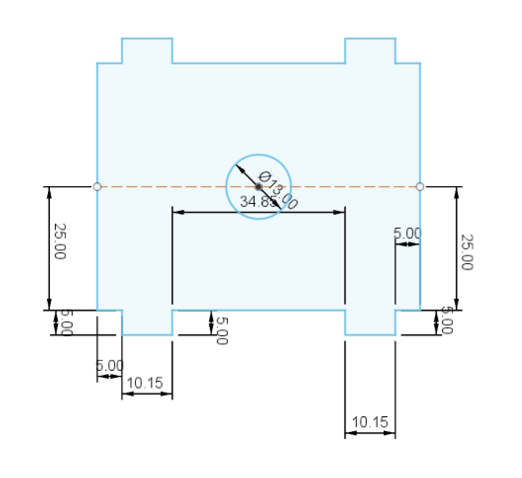
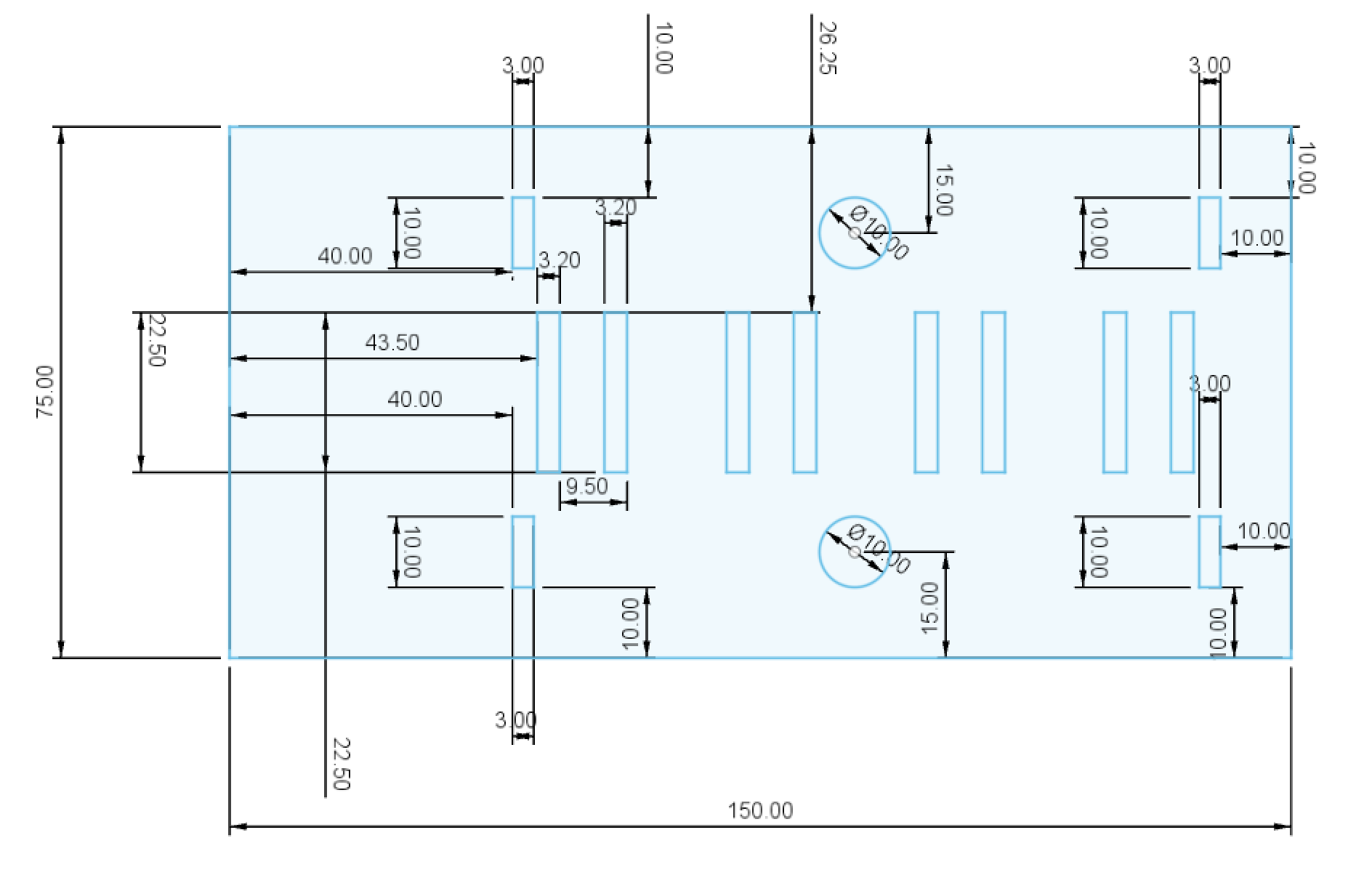
Fig. 4.6: Design of the base for hand assembly
Now with the base designed and fabricated, the last step was attaching the hand assembly to the base, the motor/spindle to the base, and feeding/attaching the nylon threads to function as tendons. For attaching the motor to the base, I used a hand drill to make some screw holes which could then be used with some M3 25mm screws, nuts, and spaces to fix the motor in place. To attach the nylon thread to the tips of the fingers, and the spindle to the motor, I used a small amount of hot glue.
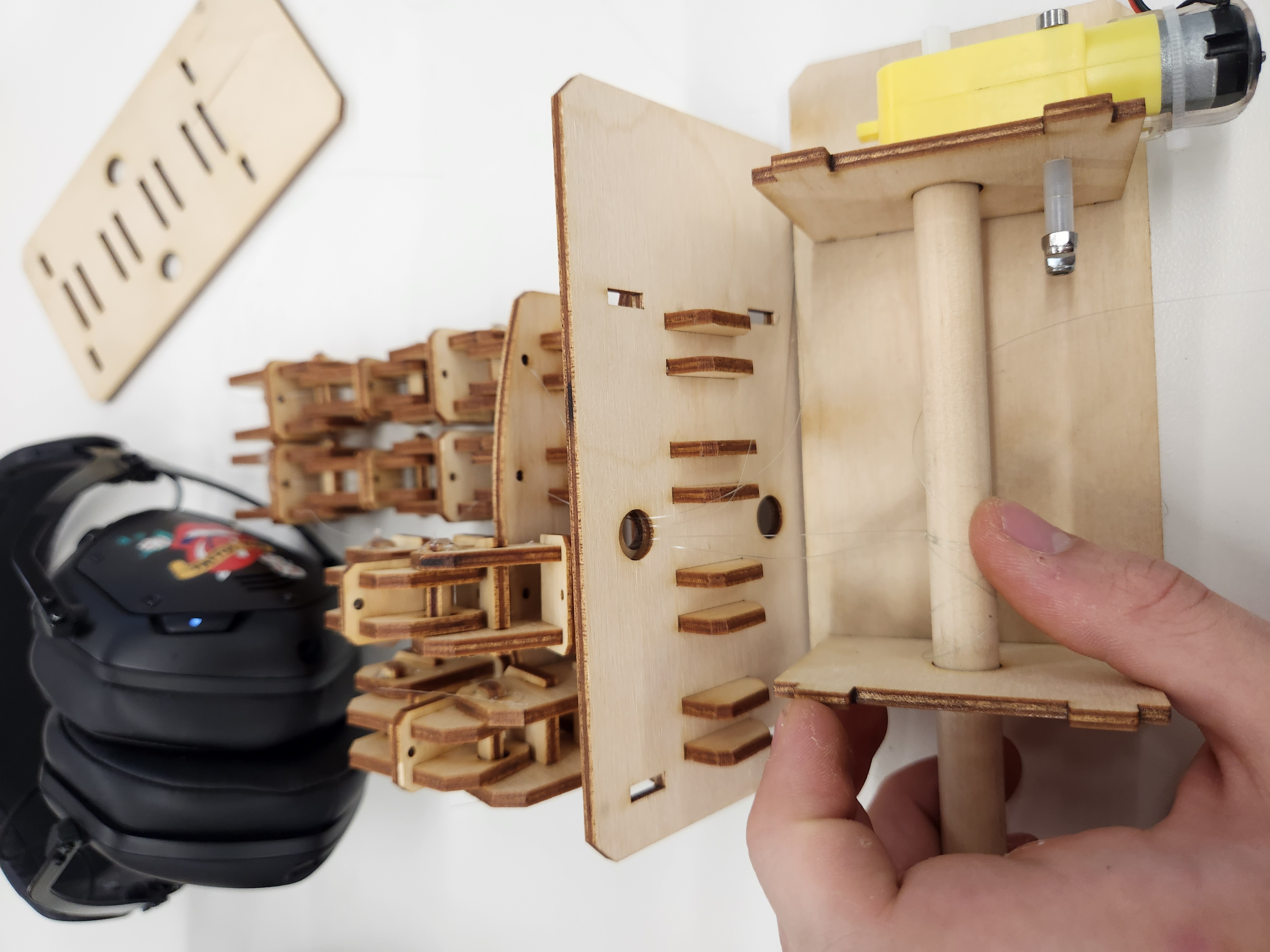
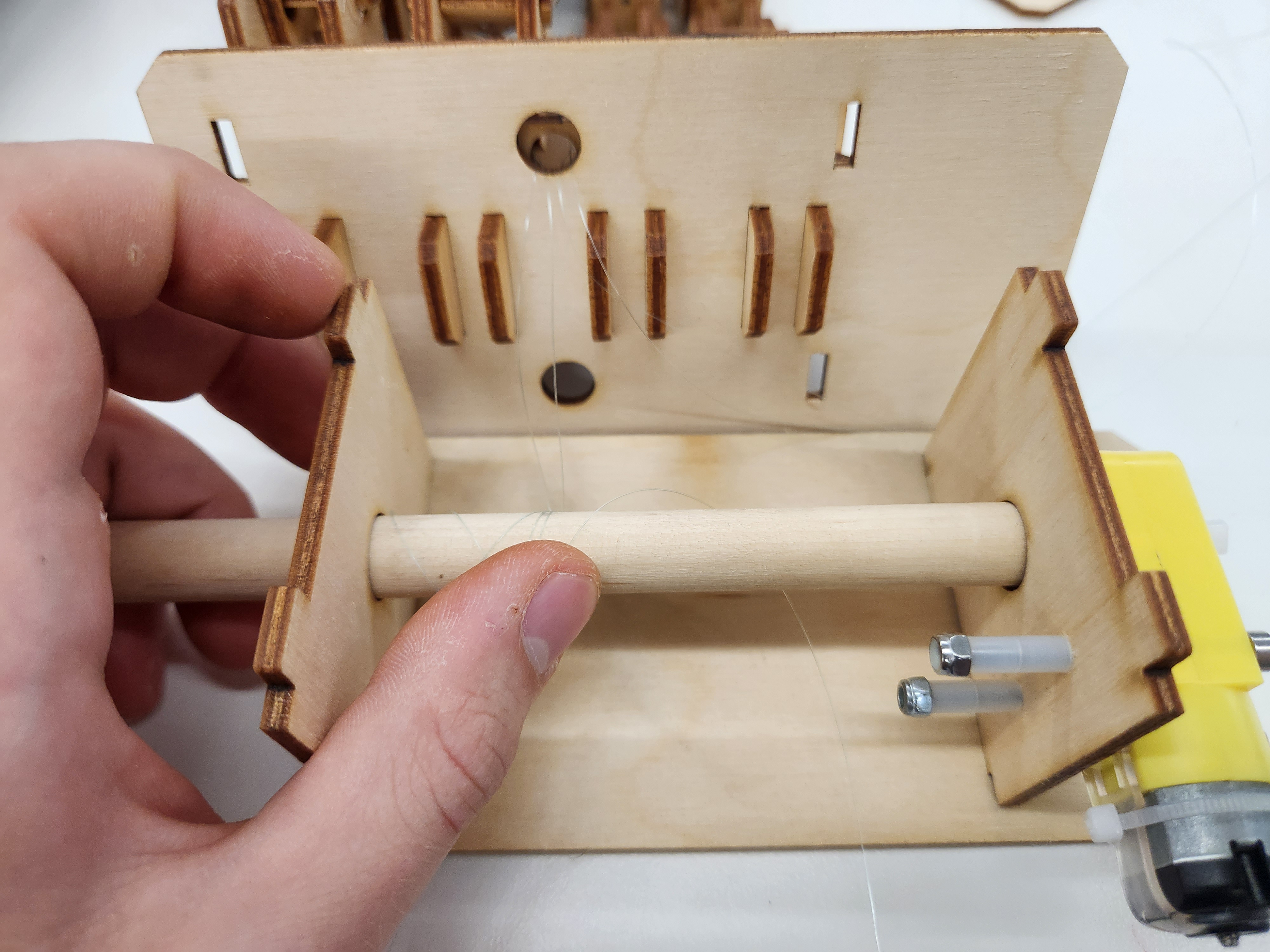
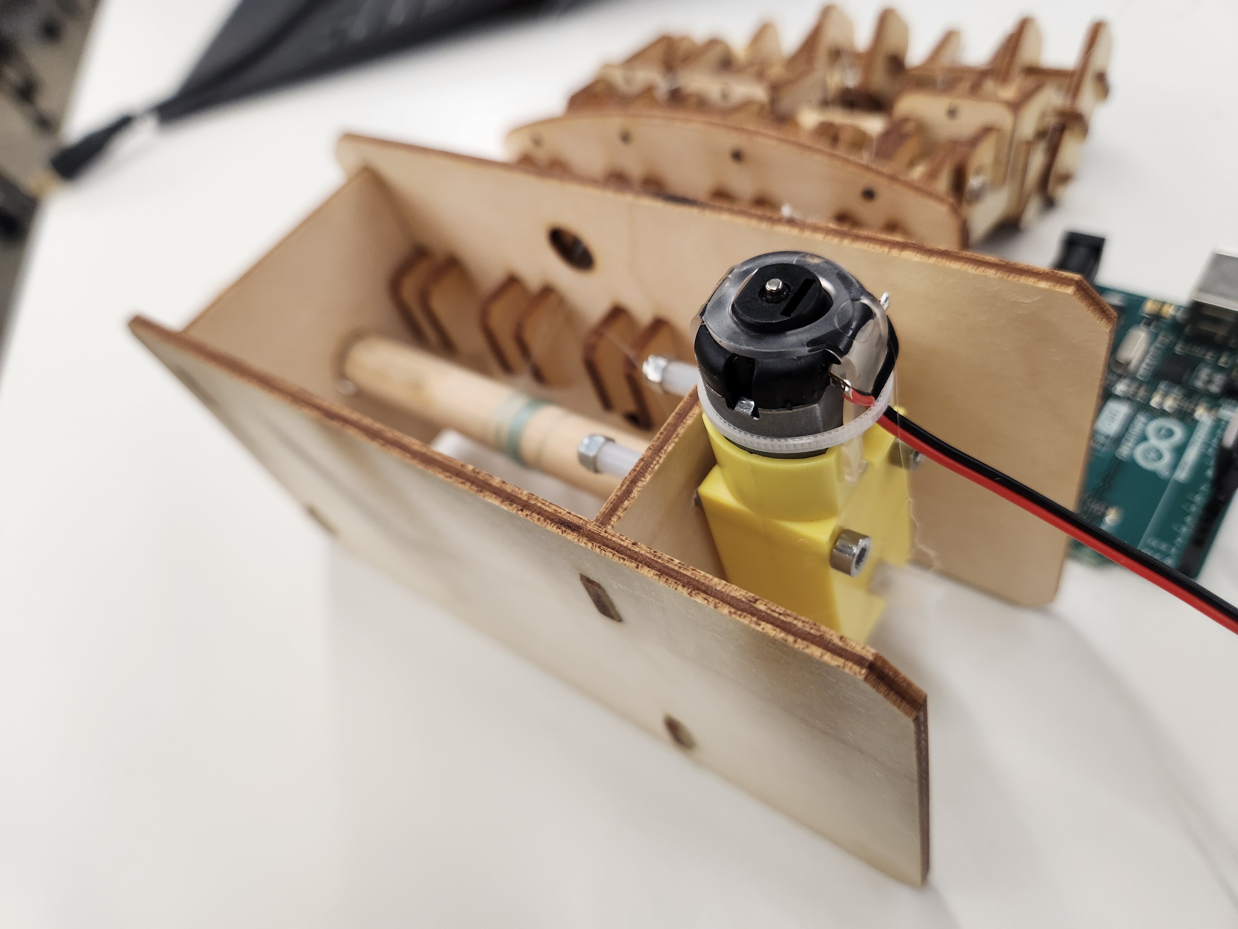
Fig. 4.7: Assembly of base and hand
The last step when it came to the mechanism itself was to finish feeding the nylon thread to the other side after winding it on the spindle. Now the assembly was complete, and it was time to make the microcontroller circuit!
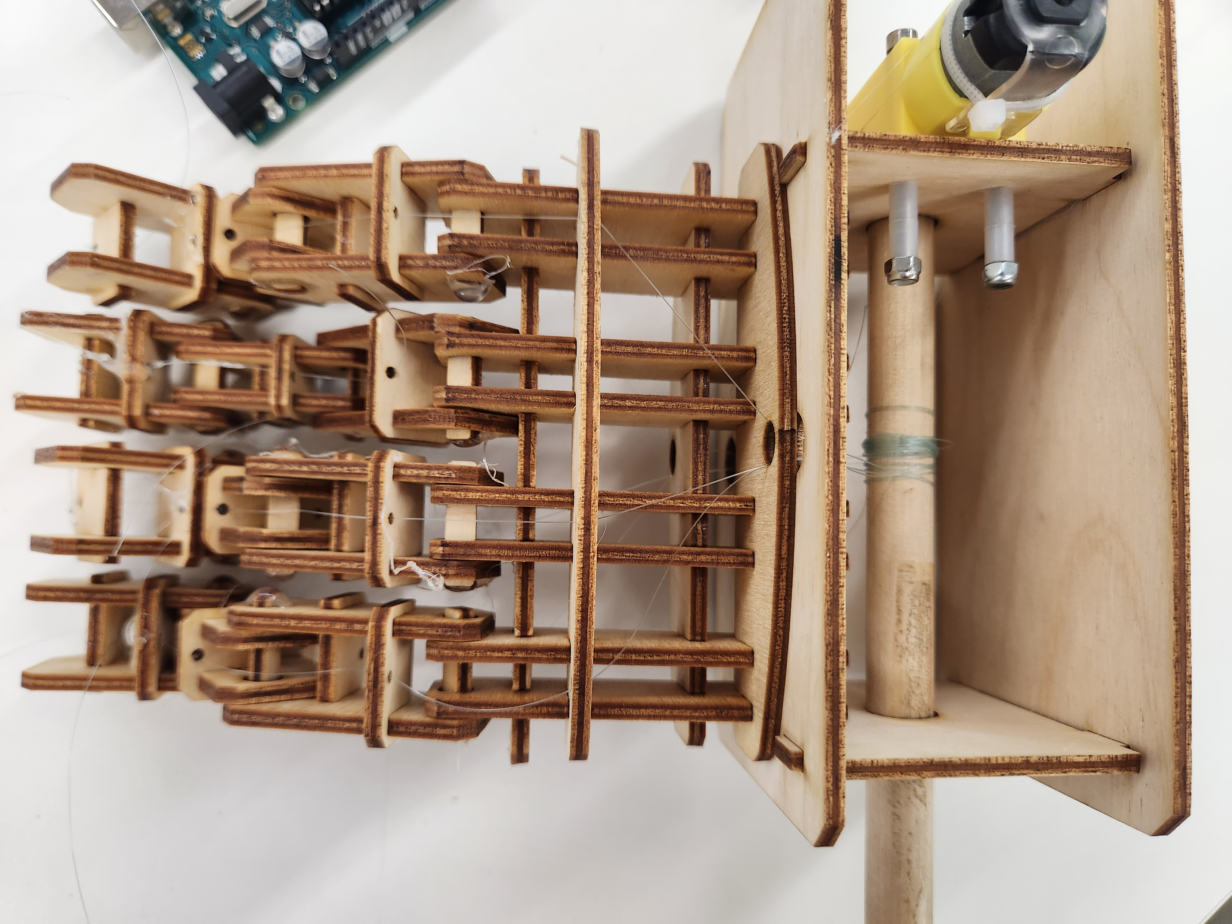
Fig. 4.8: Final product without circuitry
Microcontroller programming:
Now that the mechanics were complete, it was time to move onto the circuitry. For this project, I used an Arduino Uno microcontroller board, an L9110S motor driver, and a DC-motor with a prebuilt gearbox. For powering the DC motor, I added a seperate micro-usb pinout to the breadboard since the motor board can't run off Arduino power alone. Here's a schematic:
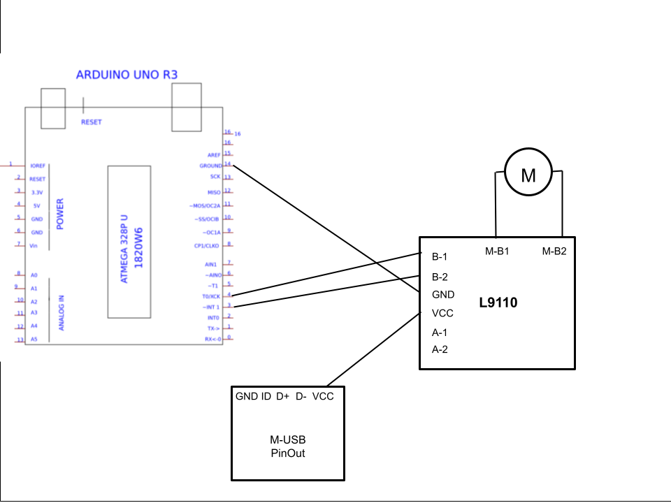
Fig. 4.9: Schematic of electronics used.
Now with the electronics done, the final step was to program it. I used some simple code in Arduino IDE that used 'digitalWrite' to send signals to the driver board, which would then spin the motor. For this project, I need the motor to spin back and forth in set intervals. Heres the code snippet:
const int A_1 = 3;
const int A_2 = 4;

void setup() {
  pinMode(A_1, OUTPUT);
  pinMode(A_2, OUTPUT);
}
 void loop(){
   digitalWrite(A_1, HIGH); // Close hand and hold closed grip for 2 sec
   digitalWrite(A_2, LOW);
   delay(2000);
   digitalWrite(A_1, LOW); // Reverse motor motion, open hand
   digitalWrite(A_2, HIGH);
   delay(1000);
   digitalWrite(A_1, LOW); // Turn off motor to loosen load, keep hand open for 1 sec
   digitalWrite(A_2, LOW);
   delay(1000);
    // Repeat
 }
Fig. 4.10: Code for sculpture
The very last step was to send the code to the Arduino and power it through the Arduino and an eternal Micro USB supply. However, there was one hitch in the process, and it ended up tearing one of the nylon threads. I think this is for the better though, as it adds some comedic value and character to the project. Heres the final product!
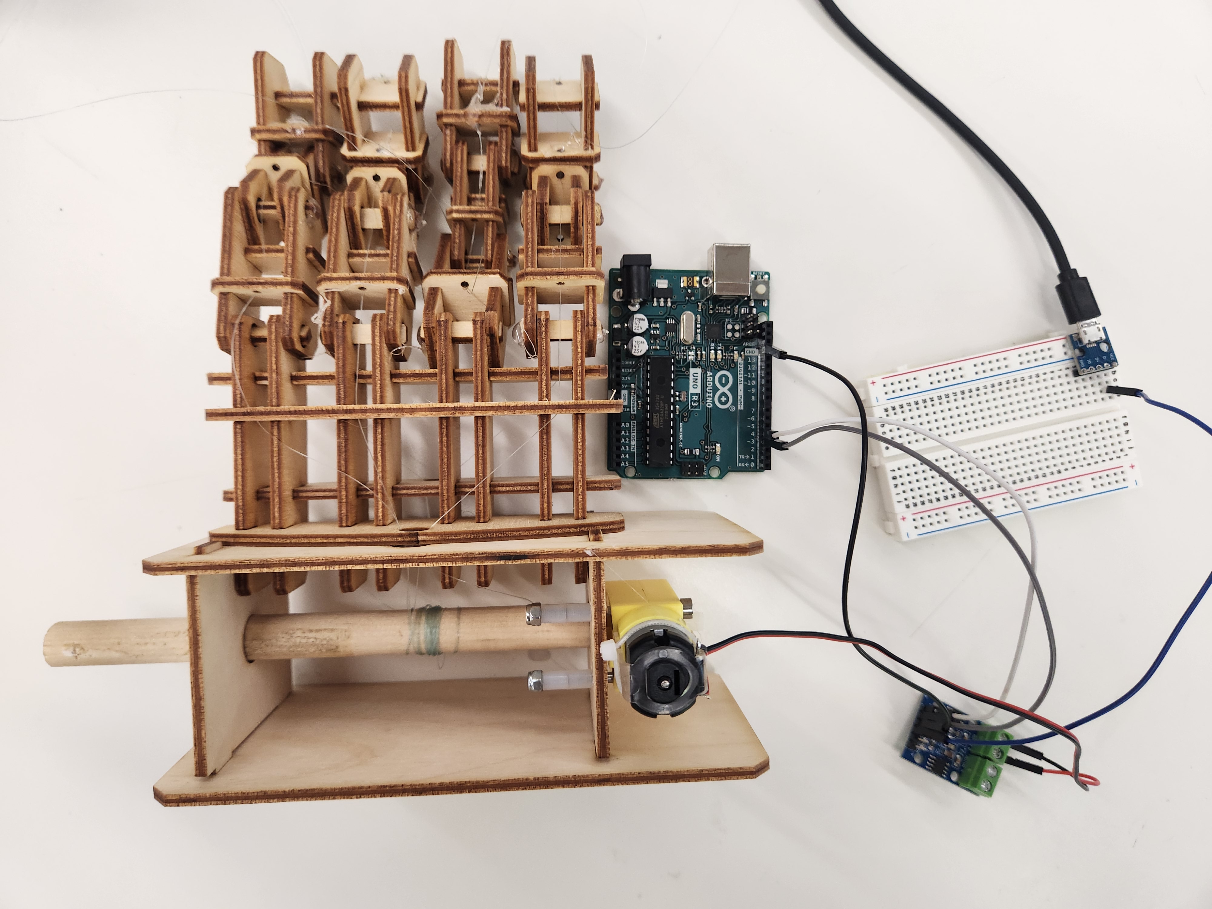
Fig. 4.11: Final Product
Using OHM's Law, I was able to determine that the current flow at its peak in the sculpture was around 800mA at 5V. It had such a high current draw when the hand was compressed and had it's full grip actuated, putting high load on the motor.