3D Scanning:
For the first half of the assignement, I needed to scan some sort of object and import it into 3D environment for printing. THe object I chose was my wallet. Using the RevoScanner software, along with a 3D scanning camera and turntable, I made a scan of my wallet in 3D, which I then fused into a mesh for editing.
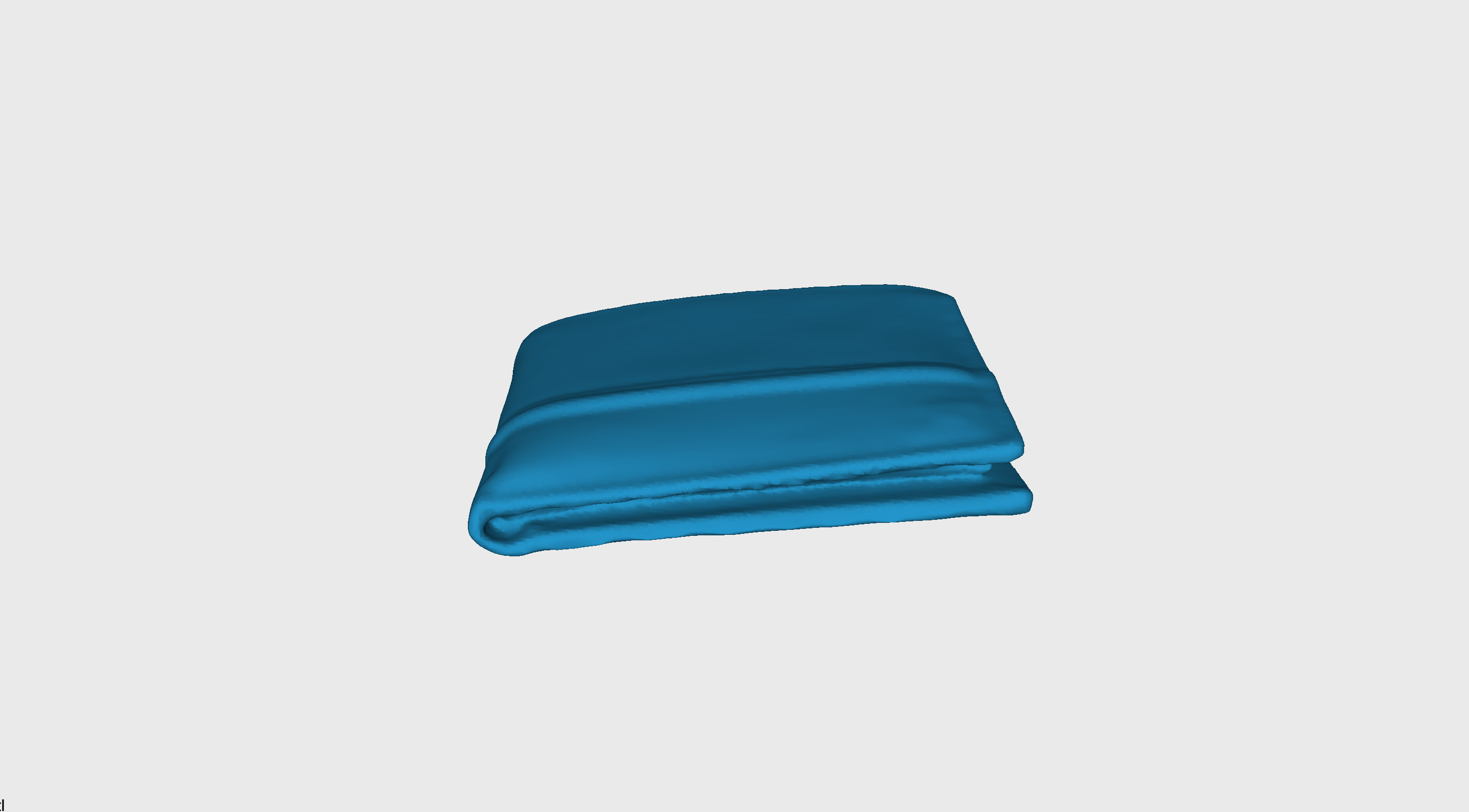
Fig. 5.1: Wallet scanned in RevoScanner
This next step involved me importing the mesh into RevoEditor, a software used for refining a 3D scan. Using this software, I trimmed excess parts of the scan and smoothed it out, creating a model I could easily print.
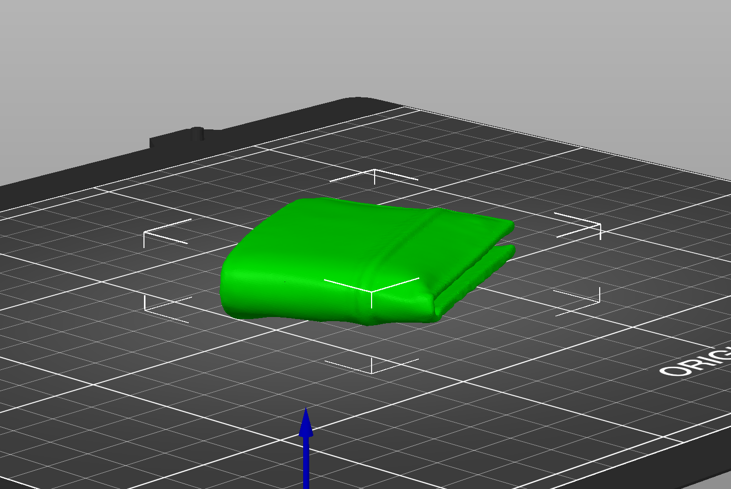
Fig. 5.2: Wallet imported into PrusaSlicer
I then opened the final model in PrusaSlicer, slicing it for the 3D printer, and downscaling the print a bit for a shorter print time of 2 hours. I loaded the G-Code on the SD card, and then printed the model on the printer.
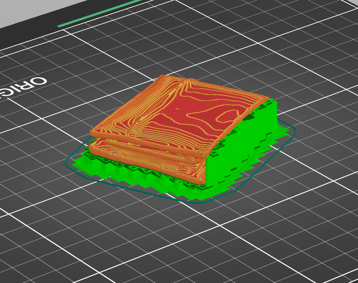
Fig. 5.3: Wallet sliced for printing
After about two hours of printing, here is the final product compared to the wallet based it off of:
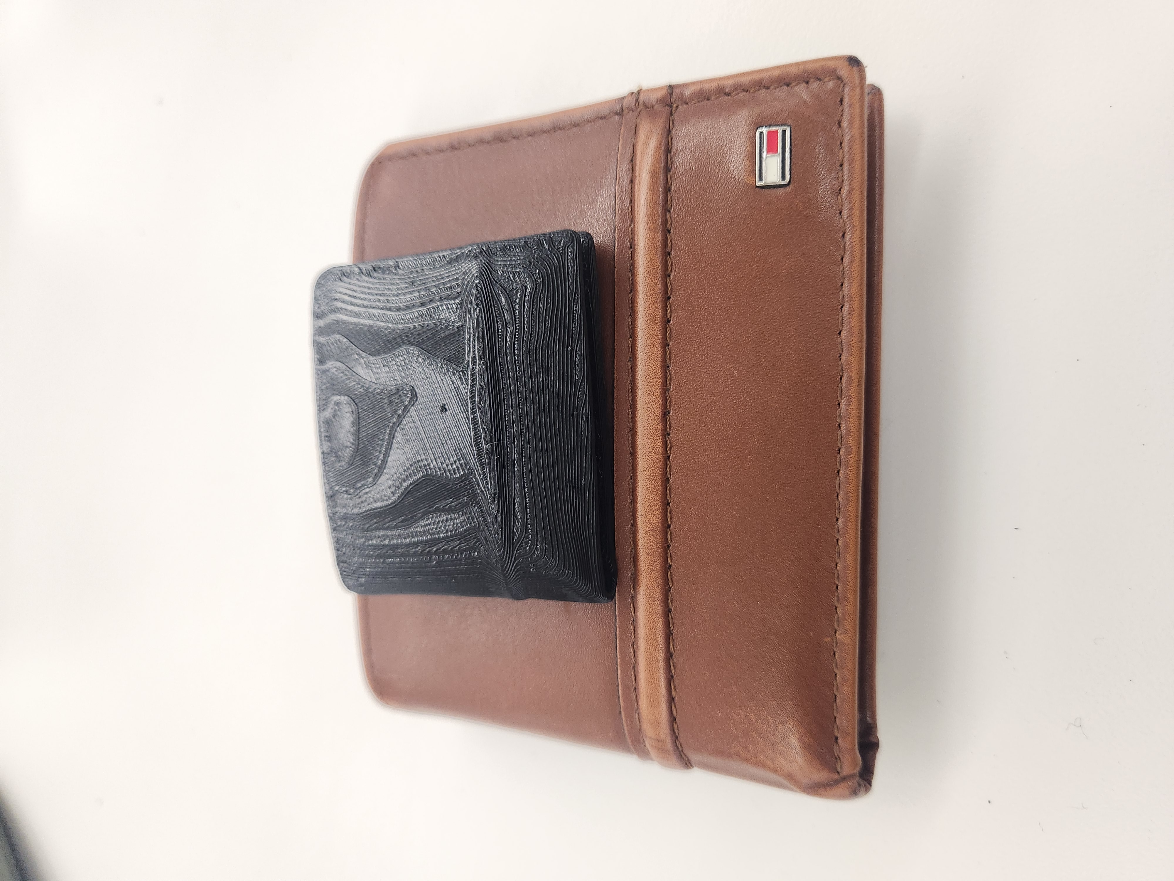
Fig. 5.4: Final product compared to reference
Modeling for 3D printing:
For my choice of model to 3D-print, I decided to model a pair of bevel gears in Fusion 360. In order to do this, i first started with two spur gears made with the built in utility. One was made with 12 teeth, and the second was made with 20 teeth
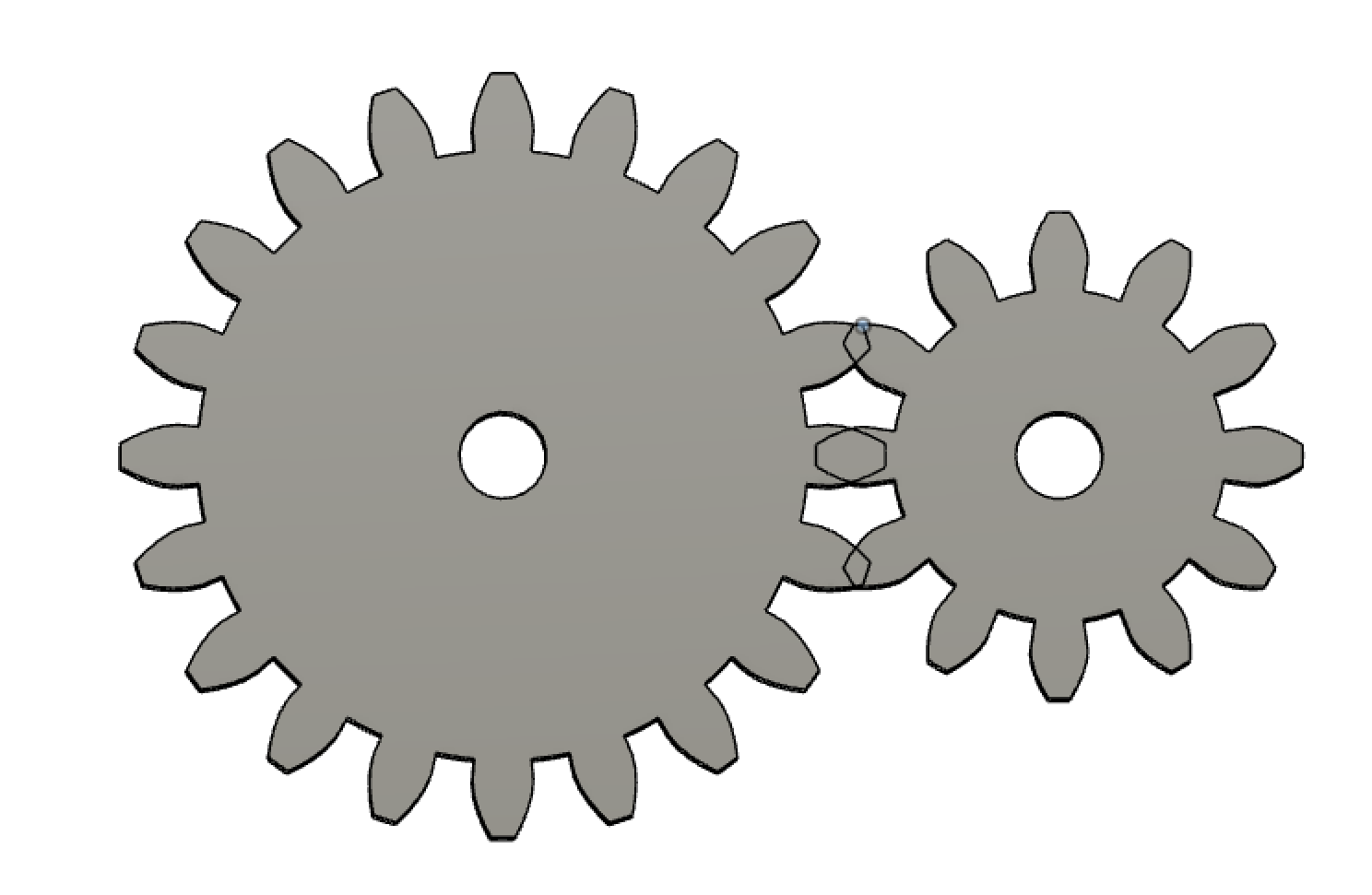
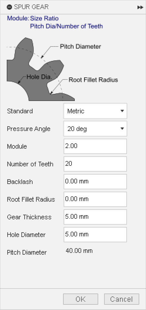
Fig. 5.5: 20 tooth and 12 tooth spur gears, made with the listed parameters
I then used some math to make a new sketch on a different plane, and used that sketch as a guide to move the gears into position for making a bevel gear at a tilt of -59 degrees.
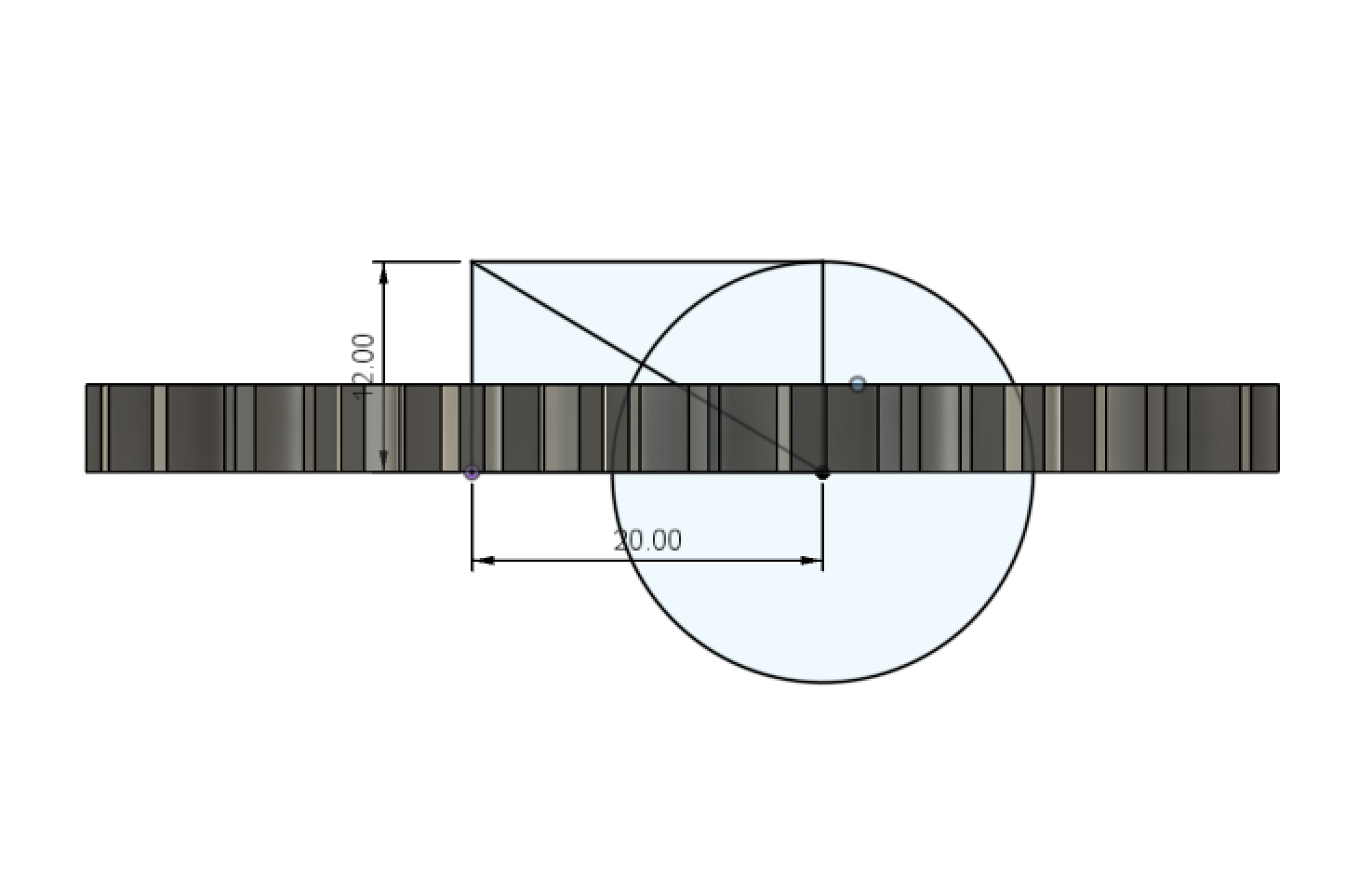
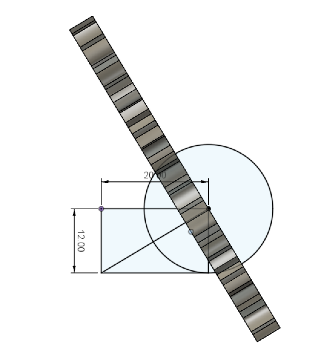
Fig. 5.6: Gear in position for beveling using another sketch
I then hid one of the gears, projected the sketch of the tooth used by the plugin to make the gear, and then lofted that shape along the line in the sketched rectangle. Then, using the circle part of the sketch, I used the Split Body tool to trim the excess of the gear tooth.
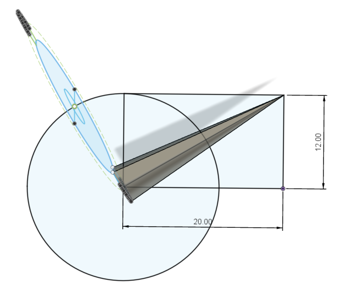
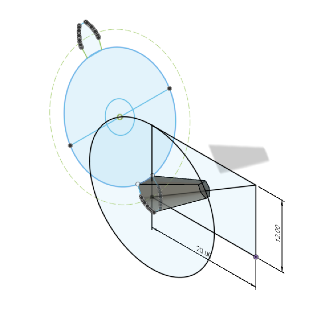
Fig. 5.7: Gear tooth made using loft tool
The next step was to sketch the profile for the gear body itself, and then use the revolve tool in order to form the body. After the revolve, the last step was to trim any excess of the gear teeth sticking out using the Split Body tool, and the using a circular pattern to evenly distribute the teeth along the gear body.
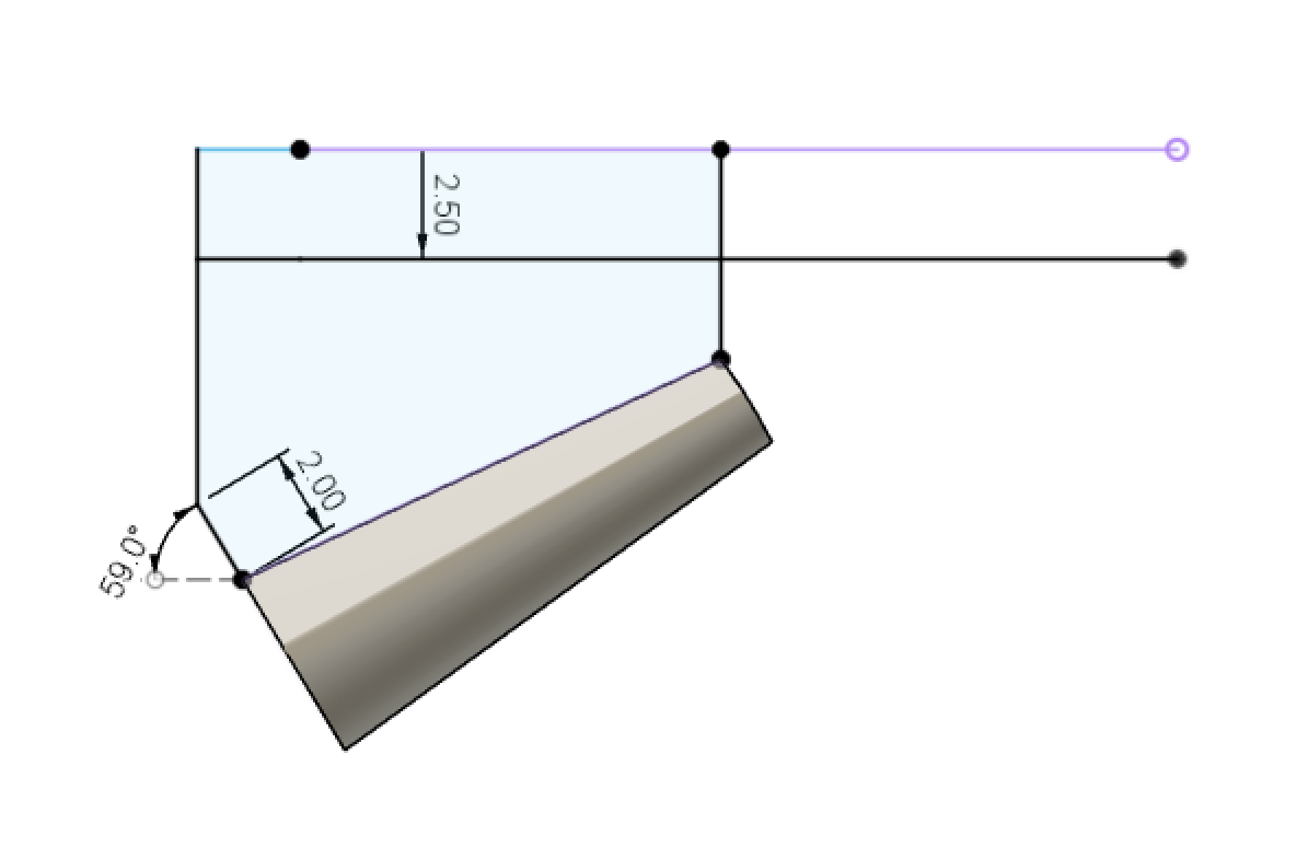
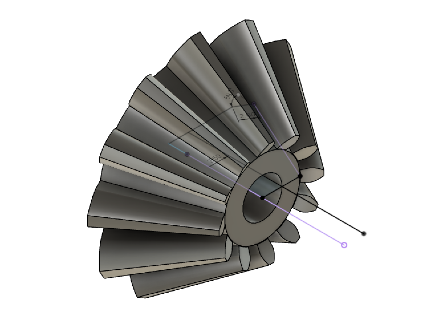
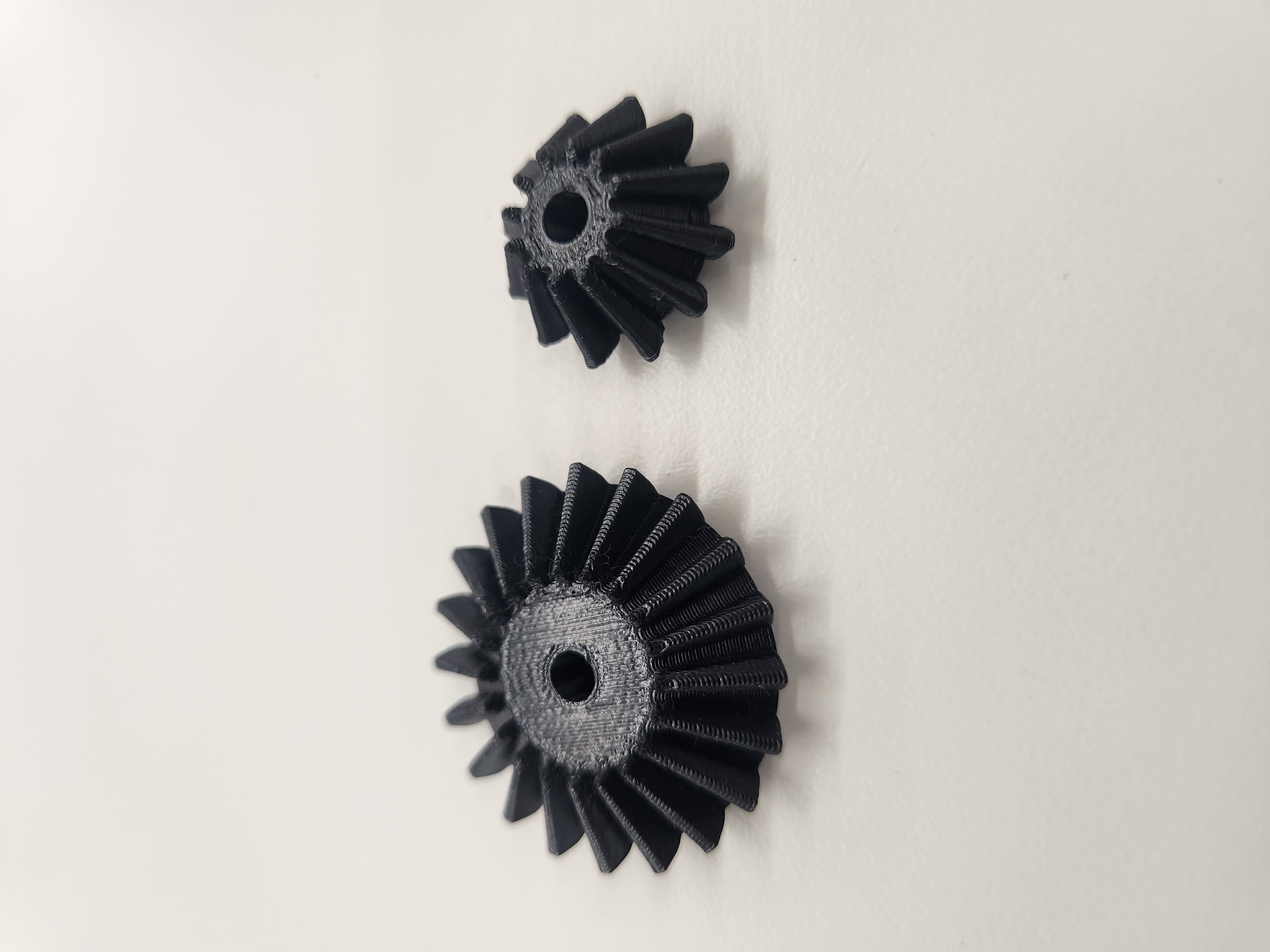
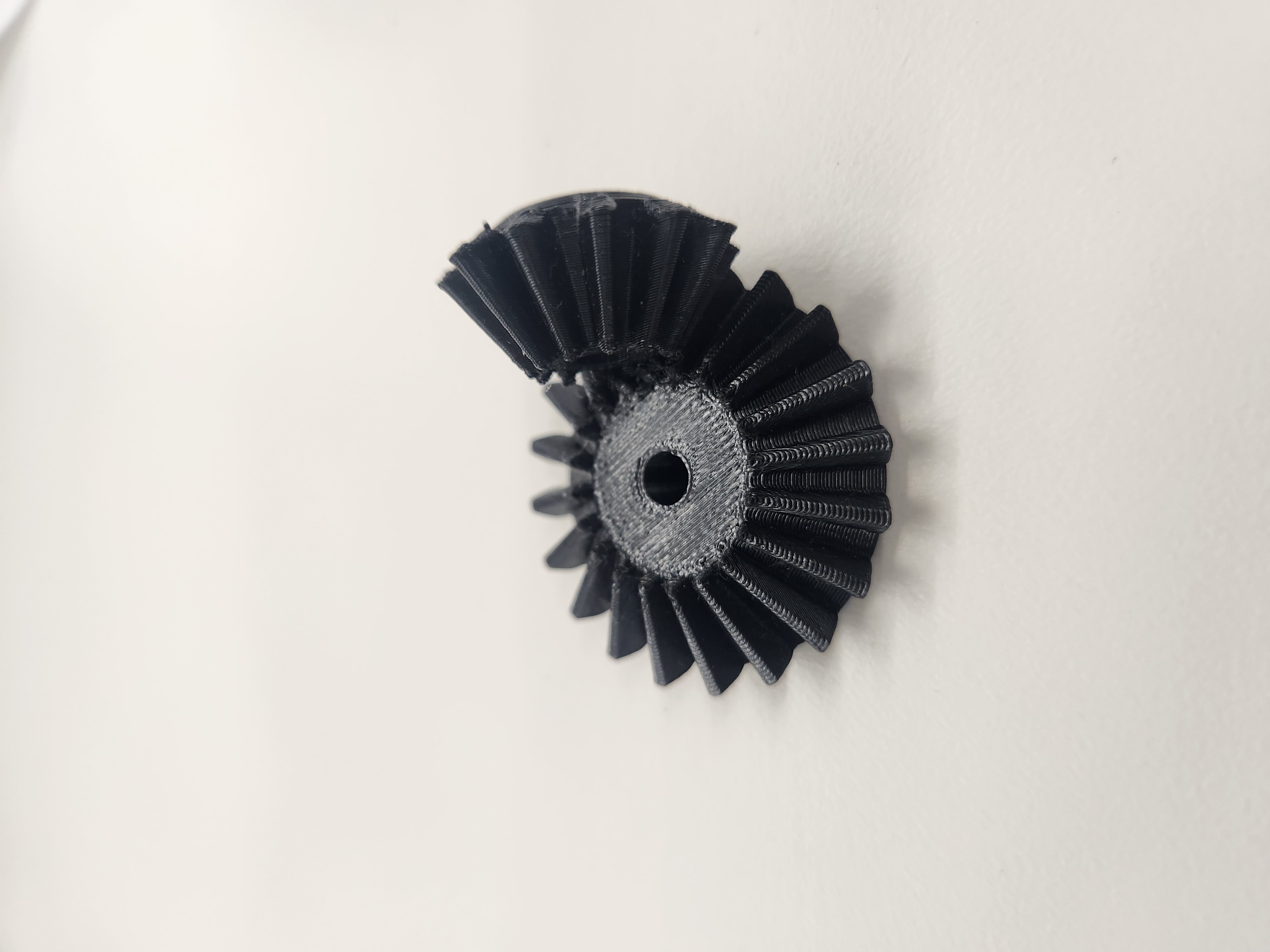
Fig. 5.8: Finished 12-tooth bevel gear
Now for the second gear, I simply repeated the process, but using the 20 toothed spur gear as my template.
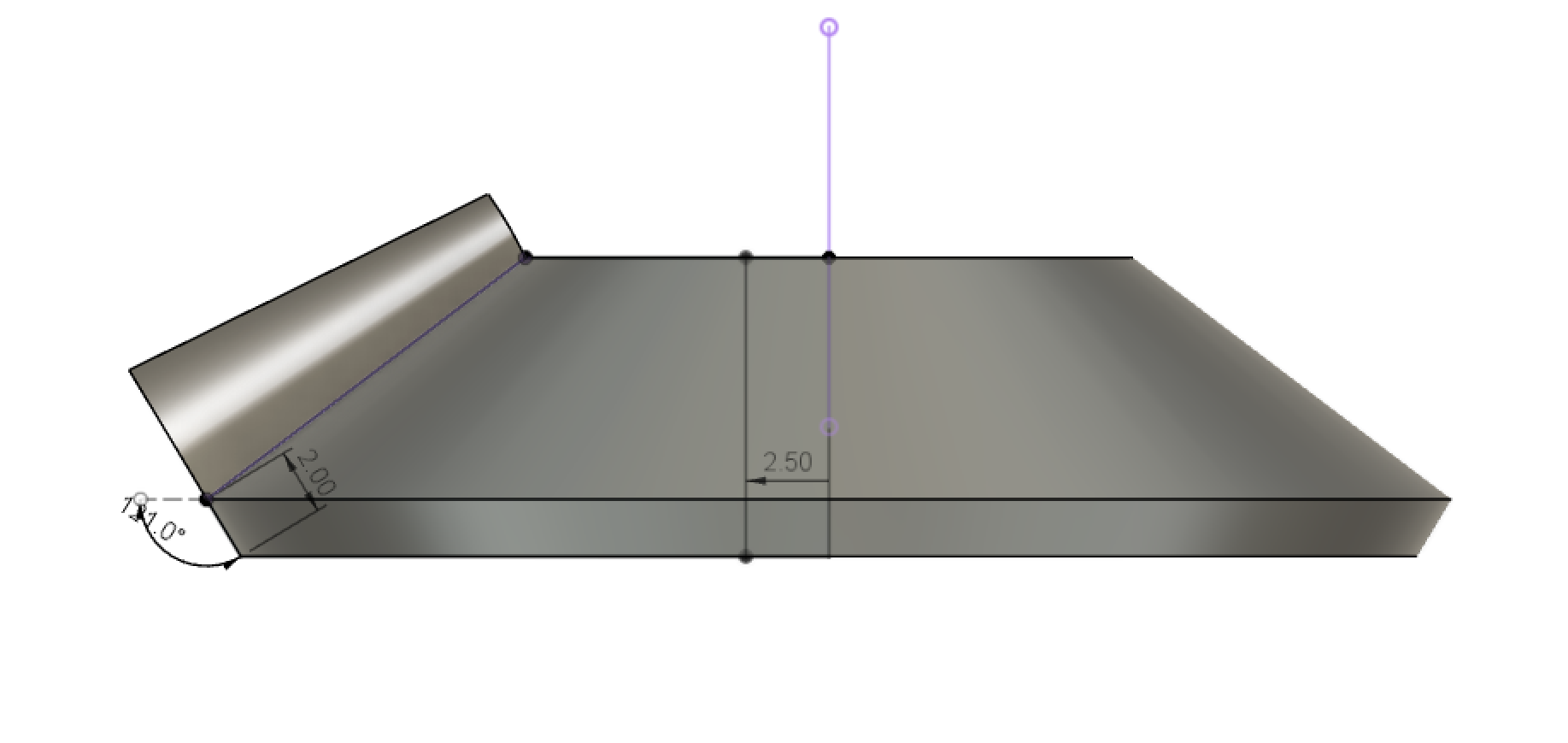
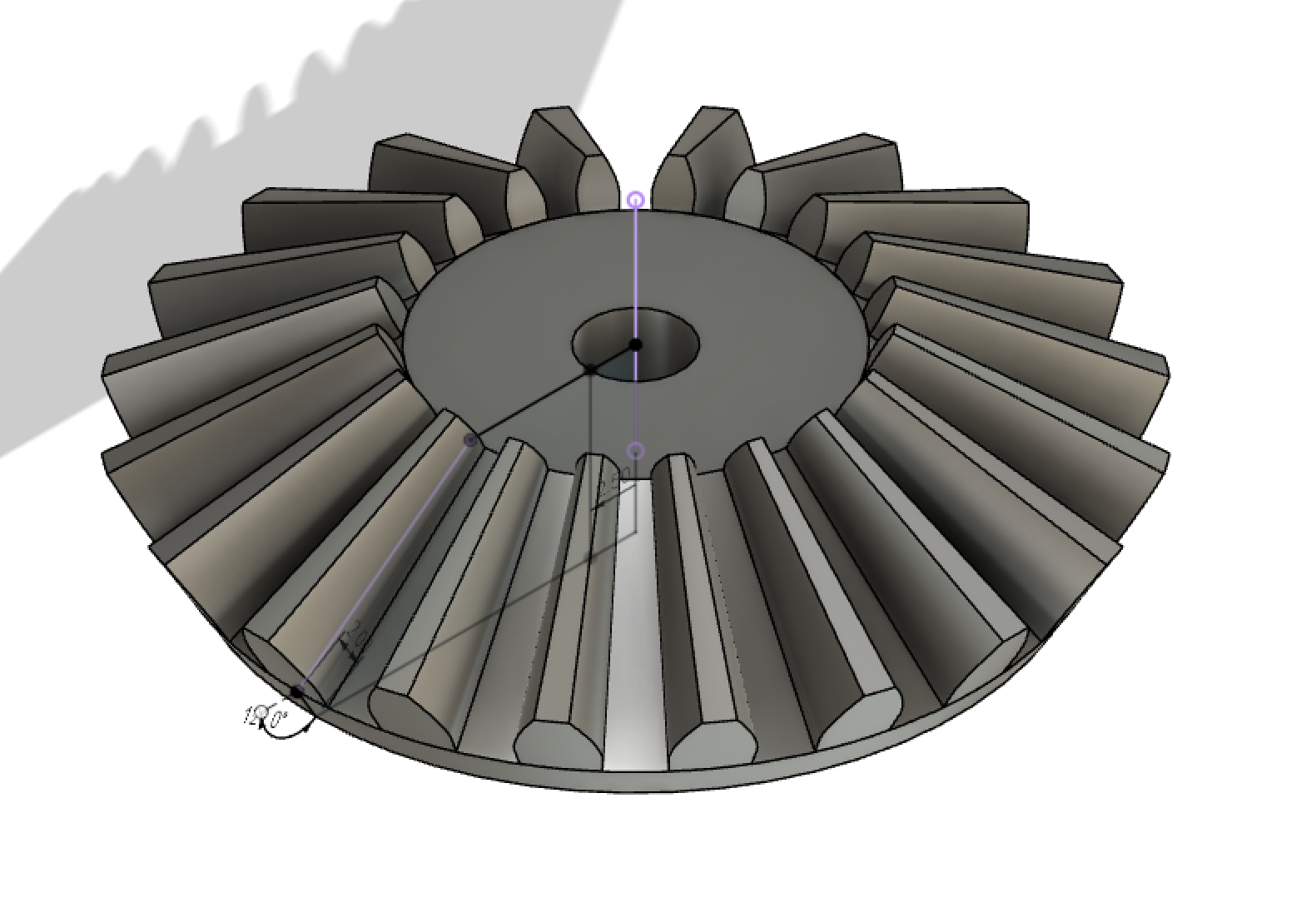
Fig. 5.9: Finished 20 tooth bevel gear
Now that the models were complete, I imported them into PrusaSlicer, sliced them using the standard 0.20mm Quality preset, exported the G-code, and transferred the files to the printer.
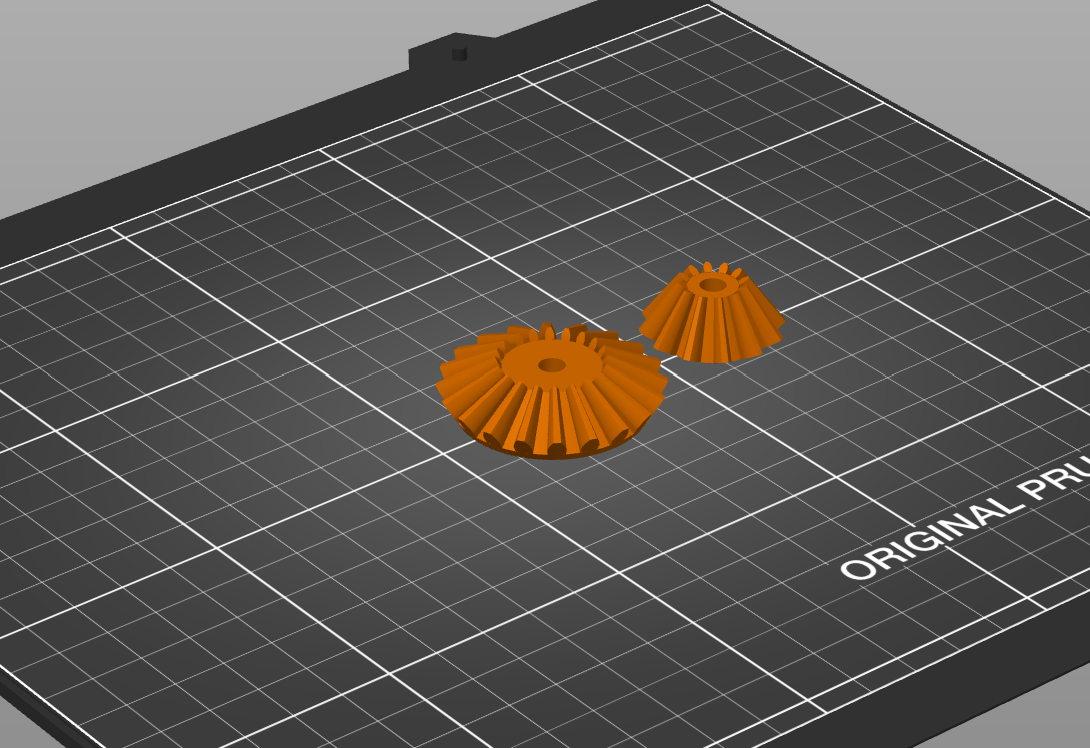
Fig. 5.10: Gears in PrusaSlicer and being printed
Here's the final result, after about 50 minutes of print time: